Soil Stack Installation: A Complete Guide
To install a soil stack, you run a vertical 110 mm PVC-U pipe from the underground drain up the outside (or inside) of the building, connecting WC and waste outlets at each floor level, and terminating above the roofline with an open vent to allow air circulation and prevent trap siphonage. The stack must comply with Building Regulations Approved Document H (drainage) and Part H’s performance requirements for above-ground drainage, including pipe sizing, branch connections, vent positioning, and support at regular intervals.
The soil stack is the main vertical artery of a building’s drainage system. Everything above ground — toilets, basins, baths, showers, kitchen sinks — ultimately discharges into the stack, which carries waste down to the underground drain and out to the sewer. It also acts as the vent for the drainage system, allowing air to enter and preventing the vacuum that would siphon water from traps.
Soil Stack Components
| Component | Purpose |
|---|---|
| Soil pipe (110 mm) | Vertical pipe carrying waste from fixtures to underground drain |
| Rest bend (87.5°) | At the base — transitions from vertical stack to horizontal drain |
| WC connection (boss or branch) | Connects toilet waste to stack |
| Waste connections (40 mm, 32 mm bosses) | Connects basin, bath, shower waste to stack |
| Pipe clips | Secure stack to wall at 1.8 m intervals |
| Weathering slate/collar | Seals where the stack passes through the roof |
| Vent terminal | Top of stack — open to atmosphere, above roofline |
| Access door (optional) | Allows rodding access at lower level |
| Offset bends | If the stack needs to change position between floors |
Planning the Stack Position
External Stack
The traditional UK approach — the soil stack runs up the external wall, usually on the rear elevation. This is the simplest to install and maintain.
Advantages:
- Easy access for maintenance and repair
- No internal space lost
- No noise transmission into rooms (the stack is outside)
- Simple weatherproofing at roof penetration
Disadvantages:
- Visible on the building elevation (usually rear, so less of an issue)
- Exposed to weather — UV, frost, temperature cycling
Internal Stack
Increasingly common on modern houses and flats — the stack runs inside the building, typically in a boxed-in duct or partition wall.
Advantages:
- Not visible externally
- Protected from weather
- Shorter branch runs from fixtures
Disadvantages:
- Occupies internal space
- Noise from flushing and discharge can be audible in rooms
- Repairs require opening the duct or wall
- Must still vent through the roof
Step-by-Step Installation
Step 1: Connect to Underground Drain
The stack starts at ground level with a rest bend connecting to the 110 mm underground drain. The rest bend transitions from vertical to horizontal and sits in the trench on a granular bed.
Step 2: Build Up the Stack
Working from the bottom up:
- Fit the first vertical pipe length into the rest bend
- Add a WC branch connection at the ground-floor toilet height (centre of WC outlet, typically 180 mm above finished floor level)
- Add waste pipe connections (boss adaptors or branch fittings) for ground-floor basin, bath, kitchen, etc.
- Continue vertical pipe to first-floor level
- Add first-floor WC and waste connections
- Continue to roof level
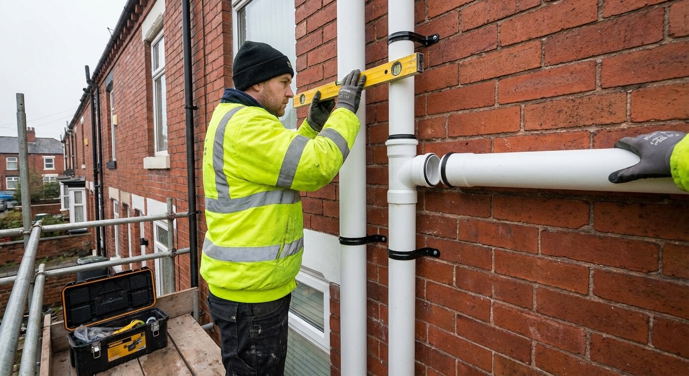
Step 3: Secure to the Wall
Fix pipe clips to the wall at maximum 1,800 mm intervals. At least one clip should be a fixed bracket (holds the pipe firm); others can be sliding brackets (allow thermal expansion movement).
Step 4: Pass Through the Roof
The stack exits through the roof tiles via a weathering slate or collar:
- Remove the tile(s) where the stack passes through
- Fit the weathering slate around the pipe — it sits over the surrounding tiles
- Replace tiles around the weathering slate
- Seal any gaps with lead flashing or proprietary sealant
Step 5: Fit the Vent Terminal
The open vent at the top of the stack must be:
- At least 900 mm above the top of any opening window within 3 m horizontally
- Open to atmosphere — fitted with a cage or mushroom cap to prevent bird nesting while allowing airflow
- Above the roofline so that prevailing winds aid the ventilation effect
Branch Connections
WC (Toilet) Connection
- Pipe size: 110 mm (same as the stack)
- Connection method: 110 mm boss or WC manifold on the stack
- Maximum branch length: 6 m from WC to stack (Approved Document H)
- Gradient: 18 mm per metre minimum (1:50)
- Entry angle: Should enter the stack at an angle that directs flow downward (usually 92.5° swept tee)
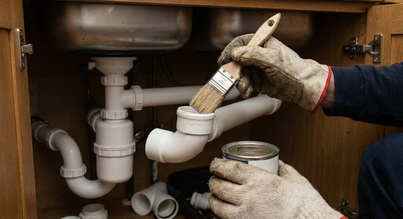
Waste Pipe Connections (Basin, Bath, Shower, Sink)
- Pipe sizes: 32 mm (basin), 40 mm (bath, shower, sink)
- Connection method: Boss adaptor drilled into the stack, or pre-formed branch fitting
- Maximum branch length: 1.7 m (32 mm), 3 m (40 mm) — Approved Document H
- Gradient: 18–90 mm per metre (1:12 to 1:50)
- Entry angle: Must enter the stack above the centreline of the WC branch connection below, or at least 200 mm above the invert of the WC connection
Branch Connection Rules
- No waste branch should connect to the stack within 200 mm below the WC connection on the same floor (risk of cross-flow)
- Connections opposite each other on the stack are acceptable if at different heights
- Multiple waste connections at the same level should use a manifold fitting
Venting
The soil stack vent performs two critical functions:
-
Prevents trap siphonage — when a large volume of water (e.g., a toilet flush) flows past a branch connection, it can create a vacuum that sucks water out of nearby traps, breaking the seal and allowing sewer gas to enter the building. The vent allows air in to prevent this.
-
Allows air circulation — air flowing through the open vent helps waste flow smoothly through the stack and the drain below.
Air Admittance Valves (AAVs) — Alternative to Full Vent
An AAV allows air into the stack under negative pressure but closes to prevent sewer gas escaping. It can replace the open vent on internal stacks, reducing the need for a roof penetration. See our guide to air admittance valves vs open vents.
Building Regulations Requirements
| Requirement | Detail |
|---|---|
| Pipe size | 100 mm minimum (110 mm pipe) for stacks serving WCs |
| Vent terminal height | 900 mm above any window within 3 m |
| Pipe support | Clips at maximum 1.8 m centres |
| Access | Rodding access at base of stack (access door or inspection chamber) |
| Branch lengths | As per Approved Document H tables |
| Material | PVC-U to BS EN 1329 (above ground) or equivalent |
Frequently Asked Questions
How to install a soil stack?
Run a 110 mm PVC-U pipe vertically from the underground drain (via a rest bend), up the building wall, connecting WC and waste outlets at each floor level, and terminating above the roofline with an open vent. Secure to the wall at 1.8 m intervals and seal the roof penetration with a weathering slate.
What size soil pipe do I need?
110 mm is the standard for domestic properties with up to two floors. Properties with three or more floors, or multiple WCs discharging simultaneously, may need a 160 mm stack. Check Approved Document H for specific requirements based on the number of fixtures.
Can a soil stack be internal?
Yes. Internal stacks are common on modern houses and flats. They must still vent through the roof (or via an air admittance valve in certain situations). Internal stacks should be in accessible ducts for maintenance, and acoustic insulation should be considered to reduce waste noise.
How far can a toilet be from the soil stack?
A WC can be up to 6 m from the soil stack on a 110 mm branch at a minimum gradient of 1:50. Longer runs require a larger branch or a separate stack. The branch should have as few bends as possible.
Do I need Building Control for a new soil stack?
Yes. A new soil stack is building work that requires Building Regulations approval. Notify Building Control before starting. They will inspect the installation, particularly the underground connection, branch connections, vent terminal height, and overall compliance with Approved Document H.